
Pi Pico C/C++ SDK 환경에서 GPIO토글 속도 측정 결과와 비교해서 Arduino 환경보다 빠른것 같은데 SPI 속도도 측정해서 비교해 보자
W6100과 같은 SPI의 전송 속도가 이더넷 전송률에 영향을 미치는 어플리케이션을 위해 SDK환경에서 SPI 테스트를 해 둘 필요가 있을것 같다.
SDK 환경에서 SPI 전송 테스트를 해보면 SPI Bye 전송 지연은 680ns로 Arduino 환경과 비슷하게 측정이 된다.

#include <stdio.h>
#include "pico/binary_info.h"
#include "pico/stdlib.h"
#include "hardware/spi.h"
#include "hardware/uart.h"

// SPI Defines
// We are going to use SPI 0, and allocate it to the following GPIO pins
// Pins can be changed, see the GPIO function select table in the datasheet for information on GPIO assignments
#define SPI_PORT spi0
#define PIN_MISO 16
#define PIN_CS   17
#define PIN_SCK  18
#define PIN_MOSI 19


void spi_initialize(void)
{
    spi_init(SPI_PORT, 37.5 * 1000 * 1000);

    gpio_set_function(PIN_SCK, GPIO_FUNC_SPI);
    gpio_set_function(PIN_MOSI, GPIO_FUNC_SPI);
    gpio_set_function(PIN_MISO, GPIO_FUNC_SPI);

    // make the SPI pins available to picotool
    bi_decl(bi_3pins_with_func(PIN_MISO, PIN_MOSI, PIN_SCK, GPIO_FUNC_SPI));
}


int main()
{
    unsigned char  buffer[10];
    stdio_init_all();

    // SPI initialisation.
    spi_initialize();

    // Chip select is active-low, so we'll initialise it to a driven-high state
    gpio_init(PIN_CS);
    gpio_set_dir(PIN_CS, GPIO_OUT);
    gpio_put(PIN_CS, 1);

    gpio_init(25);
    gpio_set_dir(25, GPIO_OUT);
    gpio_put(25, 0);

    while (true) {
        spi_write_blocking(SPI_PORT, buffer, 2);
        spi_write_blocking(SPI_PORT, buffer, 2);
    }
}
옵티마이즈 옵션을 최대로 해서 측정해 보자
# Add executable. Default name is the project name, version 0.1
set(CMAKE_C_FLAGS "${CMAKE_C_FLAGS} -O3")
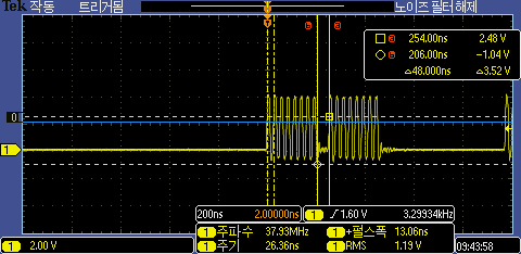
컴파일 옵티마이즈후 SPI Byte전송 지연이 48ns로 빨라 졌다. Arduino 환경에서 DMA를 사용한것과 거의 동일하게 빨라 졌다.
그렇다면 DMA를 사용한다면 더 빨라 지려나?
RP2350에서 SPI DMA를 이용한 전송 테스트를 해 보자
#include <stdio.h>
#include "pico/binary_info.h"
#include "pico/stdlib.h"
#include "hardware/spi.h"
#include "hardware/uart.h"


// SPI Defines
// We are going to use SPI 0, and allocate it to the following GPIO pins
// Pins can be changed, see the GPIO function select table in the datasheet for information on GPIO assignments
#define SPI_PORT spi0
#define PIN_MISO 16
#define PIN_CS   17
#define PIN_SCK  18
#define PIN_MOSI 19


#define USE_SPI_DMA


#ifdef USE_SPI_DMA
#include "hardware/dma.h"

static uint dma_tx;
static uint dma_rx;
static dma_channel_config dma_channel_config_tx;
static dma_channel_config dma_channel_config_rx;

void spi_write_dma(uint8_t *pBuf, uint16_t len)
{
    uint8_t dummy_data;


    channel_config_set_read_increment(&dma_channel_config_tx, true);
    channel_config_set_write_increment(&dma_channel_config_tx, false);
    dma_channel_configure(dma_tx, &dma_channel_config_tx,
                          &spi_get_hw(SPI_PORT)->dr, // write address
                          pBuf,                      // read address
                          len,                       // element count (each element is of size transfer_data_size)
                          false);                    // don't start yet


    channel_config_set_read_increment(&dma_channel_config_rx, false);
    channel_config_set_write_increment(&dma_channel_config_rx, false);
    dma_channel_configure(dma_rx, &dma_channel_config_rx,
                          &dummy_data,               // write address
                          &spi_get_hw(SPI_PORT)->dr, // read address
                          len,                       // element count (each element is of size transfer_data_size)
                          false);                    // don't start yet


    dma_start_channel_mask((1u << dma_tx) | (1u << dma_rx));
    dma_channel_wait_for_finish_blocking(dma_rx);
}
#endif


void spi_initialize(void)
{
    spi_init(SPI_PORT, 37.5 * 1000 * 1000);

    gpio_set_function(PIN_SCK, GPIO_FUNC_SPI);
    gpio_set_function(PIN_MOSI, GPIO_FUNC_SPI);
    gpio_set_function(PIN_MISO, GPIO_FUNC_SPI);


    // make the SPI pins available to picotool
    bi_decl(bi_3pins_with_func(PIN_MISO, PIN_MOSI, PIN_SCK, GPIO_FUNC_SPI));


    #ifdef USE_SPI_DMA
    dma_tx = dma_claim_unused_channel(true);
    dma_rx = dma_claim_unused_channel(true);


    dma_channel_config_tx = dma_channel_get_default_config(dma_tx);
    channel_config_set_transfer_data_size(&dma_channel_config_tx, DMA_SIZE_8);
    channel_config_set_dreq(&dma_channel_config_tx, DREQ_SPI0_TX);


    // We set the inbound DMA to transfer from the SPI receive FIFO to a memory buffer paced by the SPI RX FIFO DREQ
    // We coinfigure the read address to remain unchanged for each element, but the write
    // address to increment (so data is written throughout the buffer)
    dma_channel_config_rx = dma_channel_get_default_config(dma_rx);
    channel_config_set_transfer_data_size(&dma_channel_config_rx, DMA_SIZE_8);
    channel_config_set_dreq(&dma_channel_config_rx, DREQ_SPI0_RX);
    channel_config_set_read_increment(&dma_channel_config_rx, false);
    channel_config_set_write_increment(&dma_channel_config_rx, true);
    #endif
}


int main()
{
    unsigned char  buffer[10];
    stdio_init_all();


    // SPI initialisation.
    spi_initialize();

    // Chip select is active-low, so we'll initialise it to a driven-high state
    gpio_init(PIN_CS);
    gpio_set_dir(PIN_CS, GPIO_OUT);
    gpio_put(PIN_CS, 1);


    gpio_init(25);
    gpio_set_dir(25, GPIO_OUT);
    gpio_put(25, 0);

    while (true) {
        #ifdef USE_SPI_DMA
        spi_write_dma(buffer, 2);
        spi_write_dma(buffer, 2);
        #else
        spi_write_blocking(SPI_PORT, buffer, 2);
        spi_write_blocking(SPI_PORT, buffer, 2);
        #endif

        sleep_ms(10);
    }
}
DMA 사용시 48ns로 10배이상 빨라진다.

옵티마이즈 했을 경우 DMA 블럭 전송 지연은 440ns로 측정이 된다.

옵티마이즈 옵션을 사용하지 않으면 6200ns로 느려진다.

반응형


