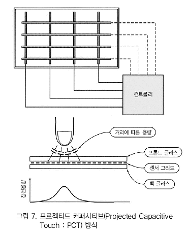
프로젝티드 커패시티브(Projected Capacitive) 방식 패널의 구조와 동작원리이다.

가로, 세로로 전극(센서 와이어)이 있는 점은 4선식의 저항막 방식과 같지만, 저항막과 같이 터치된 장소가 도통하는 것이 아니라 전극간 정전용량의 변화를 포착하 는 것이다. 나중에 설명하는 터치 스위치에서 사용되는 정전용량검출 방식의 2차원 확장판으로 볼 수도 있을 것이다.
인체는 물이 많으므로 도전성이 있다. 그림과 같이 가로, 세로 로 되어 있는 전극에 인체가 가까이 가면 손가락과 전극 사이의 정전용량이 증가한다. 가로, 세로의 어떤 라인간 정전용량이 크게 되어 있는지를 조사하면 어떤 교점의 근처가 터치되었는지 알 수 있는 구조이다.
저항막 방식과 같이 전극이 변형될 필요가 없으며 10mm 이상 떨어져 있어도 검출되도록 할 수 있다. 표면을 글라스로 커버할 수 있기 때문에 흠집에도 강하여 내구성이 나 내환경성에 우수하다. 한편, 정전용량의 변화가 거의 일어나지 않는 절연물을 근접 시켜도 검출되지 않기 때문에 장갑을 낀 상태에서는 감지할 수 없다는 등의 결점을 갖고 있다.
정전용량식 터치 센서
정전용량식 터치 센서의 기본적인 개념은 프로젝티드 커패시 티브 방식과 같으며 전극간 정전용량의 변화를 잡으려는 것이다
(그림 9). 전극은 프린트 기판상의 패턴으로 형성하면 되고, 위에 솔더 레지스터 등이 피복되어 있어도 상관없다. 통상적으로는 한쪽은 그라운드로 하고 또 한쪽은 검출용 전극으로 한다.
그림 10은 실제 버튼과 검출거리의 일례이다. 버튼 형상이나 치수에 따라 검출할 수 있는 거리도 변화한다. 거리가 길면 잘못 된 조작 등으로 연결되고, 너무 짧으면 아무리 눌러도 반응하지 않을 수 있으므로 용도나 기기의 형상 등으로 패턴을 조정한다.
그림 10(d)에서 톱니가 나란히 있는 것과 같은 것은 슬라이더용 패턴이며, 손가락이 수평방향의 어느 주변에 있는지 검출할 수 있게 한 것이다. 음악 플레이어의 선곡이나 음량조정 등 손가 락을 슬라이드시켜 조작할 수 있는 기능을 부여할 수 있다.
션트(Shunt) 방식
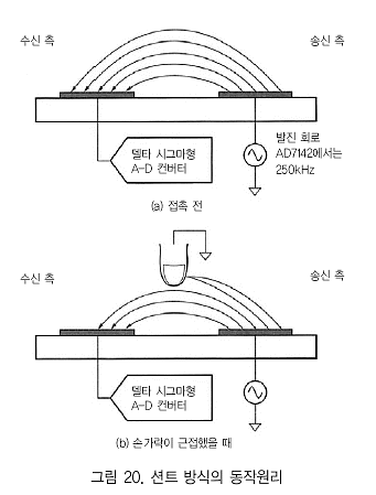
션트(Shunt) 방식은 아날로그 디바이스社의 정전용량 터치 센서 IC(AD7142 등)에서 사용되는 방식이다. 그림 20에 션트 방식의 동작 원리를 나타낸다.

이것은 무선통신과 비슷한 개념이다. 인접한 2개 패턴의 한쪽 을 송신 안테나처럼 하여 비교적 높은 주파수(AD7142인 경우에 는 250kHz)로 구동한다. 또 한쪽을 수신용 안테나로 하여 이 신호를 받고 A-D 변환한다. 그림의 위쪽과 같이 안테나끼리 전계에서 결합한 것과 같은 상태로 된다.
여기서 손가락 끝이 근접해 오면 그림 20(b)와 같이 된다. 인
체는 접지된 물체로서 행동한다. 마치 실드판이 서있는 것과 같은 상황으로 되어 수신 레벨이 저하된다.
터치 센서 IC에서는 주위 환경 변화에 보상을 실시하거나, 터
치하는 손가락의 크기 등에 따른 변화량 증감에도 대응하는ON/OFF 스레숄드 레벨 및 감도까지 자동 조정하도록 되어 있다.
(출처 : 전자기술 2008.10)
Of the technologies we describe projected capacitive touch devices are the most expensive to produce. Their erformance is rather worse than many of the other approaches we describe; however they aord superb mechanical resilience. Projected capacitive surfaces can also be covered by a nonconductive material (with a maximum thickness of around 20mm) without negatively impacting on their functionality.

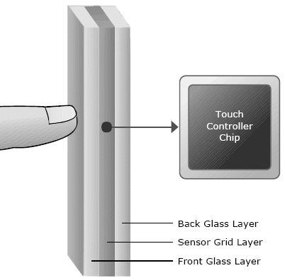
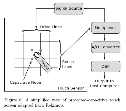
When used for (multi-) touch displays, as described by Rekimoto [32]) a very thin grid of microphone wires is installed between two protective glass layers (see gure 6). When touched, capacitance forms between the nger and the sensor grid and the touch location can be computed based on the measured electrical characteristics of the grid layer. The accuracy of projected capacitive technology is similar to surface capacitive technology although light transmission is superior because the wire grid can be constructed such that it.

Figure 5: A thin grid layer is protected by two glass layers.
Capacitance forms between the nger and the grid during a touch. The change of electrical properties is measured to
determine the touching position according [37]. is nearly transparent. The technology is also highly suitable for rugged environments such as public installations, as a protective layer (such as thick glass) may be added without drastically decreasing the sensitivity. Finally, multiple simultaneous touches can be more easily interpreted compared to surface capacitive based technology.
MERL Capacitive Diamond Touch. In 2003 Diamond-Touch was developed in the Mitsubishi Electric Research Laboratories (MERL). DiamondTouch was designed to support multiple touches, be tolerant of objects placed on the
table, durable, un-encumbering, and inexpensive to manufacture [7]. The system has a number of distinctive haracteristics: the ability to handle many touch points and users (only limited by the size of the table and the available space around it); the ability to identify which users are interacting with the surface; it is aected by debris objects like cups placed upon its surface it does not require additional devices for interaction(such as special pens).
Furthermore, the isolating layer between the antenna array and the user can be manufactured from a wide array of materials; hence it can be made to be very robust. For example, when a special bre glass laminate is used, alcohol
may be ignited on the surface without causing damage.
Using capacitive coupling DiamondTouch is composed of a table with integrated antennas transmitting unique signals,
a ceiling-mounted projector presents a display onto the table, one conductive chair connected with a receiver for each
user and a computer. \When a user touches the table, a capacitively coupled circuit is completed. The circuit runs from the transmitter, through the touch point on the table surface, and through the user to the user's receiver back to the transmitter.\ [7]. DiamondTouch works by transmitting signals through antennas in the table; these signals are used to identify the parts of the table each user is touching. This information can then be used to calculate [7] the nger's position. Usually a user touches several antennas at once. For this reason the signals have to be separable (in technical terms orthogonal). This can be achieved by frequency-division multiplexing, time-division multiplexing or code-division multiplexing. The antenna pattern consists of two layers similar in design, but with one rotated by ninety degrees. The rows/columns (antennas) of each layer are composed of diamond shapes connected in one direction and isolated in the other. In this way, the covered surface is maximised and the shielding eect minimised. Usually there is an antenna every ve millimetres (which is he resulting the minimum pointing accuracy). Due to image projection from above the only obstructions are shadows cast on the table by objects (i.e. hands or arms) inserted into the projector's light beam.
반응형


