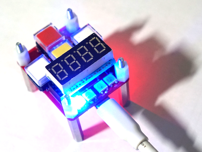
nRF54 Xbee의 PWM 테스트를 위해 Xbee 키보드 인터페이스 보드의 SK6812 LED를 제어하는 테스트를 해 보자.
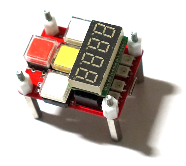
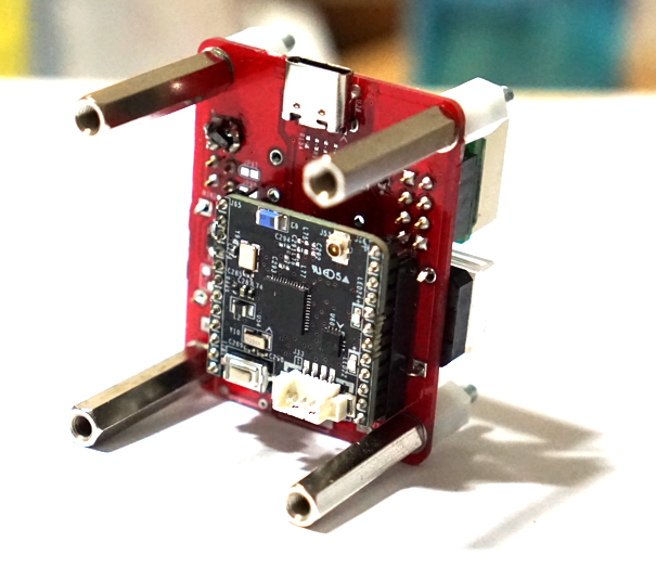
SK6812 NexPixel LED를 제어 하는 방법은 여러가지가 있지만 간단하게 PWM으로 제어할 수 있다. 우선 nRF54의 PWM 초기화 함수를 작성한다.
#include <hal/nrf_pwm.h>
#include <nrfx_pwm.h>
#include <nrfx.h>

#define SK6812_PIN          NRF_GPIO_PIN_MAP(1, 8)

#define NUM_LEDS            4
#define BITS_PER_LED        24                     // GRB 24비트
#define TOTAL_DATA_BITS     (NUM_LEDS * BITS_PER_LED)
#define RESET_BITS          80                     // >80us Low Latch 신호

// 16MHz 클럭 기준, 주기 20 Ticks = 1.25us (800kHz)
#define PWM_COUNTER_TOP     20
#define T0H_TICKS           5                      // Bit 0 High: 0.3125us
#define T1H_TICKS           11                     // Bit 1 High: 0.6875us

// EasyDMA 전송 버퍼
static uint16_t pwm_seq_values[TOTAL_DATA_BITS + RESET_BITS];

typedef struct {
    uint8_t r;
    uint8_t g;
    uint8_t b;
} ColorGRB;

static ColorGRB leds[NUM_LEDS];

// HAL API를 이용한 SK6812 PWM 초기화 (Assertion/IRQ 충돌 및 리셋 완벽 방지)
void sk6812_init(void)
{
    // 1. P1.08 핀을 GPIO 출력으로 설정
    nrf_gpio_cfg_output(SK6812_PIN);
    nrf_gpio_pin_clear(SK6812_PIN);

    // 2. PWM20 비활성화 후 재설정
    nrf_pwm_disable(NRF_PWM20);

    // 3. P1.08 핀을 PWM20 채널 0에 직접 할당
    uint32_t pins[NRF_PWM_CHANNEL_COUNT] = {
        SK6812_PIN,
        NRF_PWM_PIN_NOT_CONNECTED,
        NRF_PWM_PIN_NOT_CONNECTED,
        NRF_PWM_PIN_NOT_CONNECTED
    };
    nrf_pwm_pins_set(NRF_PWM20, pins);

    // 4. PWM 기본 동작 설정 (16MHz, Up Counter, Top = 20)
    nrf_pwm_configure(NRF_PWM20, NRF_PWM_CLK_16MHz, NRF_PWM_MODE_UP, PWM_COUNTER_TOP);

    // 5. 로드 모드 및 스텝 모드 설정
    nrf_pwm_decoder_set(NRF_PWM20, NRF_PWM_LOAD_COMMON, NRF_PWM_STEP_AUTO);

    // 6. PWM20 하드웨어 활성화
    nrf_pwm_enable(NRF_PWM20);

    printk("SK6812 PWM20 HAL Initialized successfully!\n");
}
SK6812 NexPixel LED를 제어 하는 함수를 작성한다.
// LED 색상 지정
void sk6812_set_pixel(uint8_t index, uint8_t r, uint8_t g, uint8_t b)
{
    if (index < NUM_LEDS) {
        leds[index].r = r;
        leds[index].g = g;
        leds[index].b = b;
    }
}

// HAL EasyDMA 직접 트리거 전송
void sk6812_show(void)
{
    uint32_t bit_idx = 0;

    for (int i = 0; i < NUM_LEDS; i++) {
        // SK6812 GRB 순서 전송 (MSB First)
        uint32_t color = ((uint32_t)leds[i].g << 16) |
                         ((uint32_t)leds[i].r << 8)  |
                         ((uint32_t)leds[i].b);

        for (int b = 23; b >= 0; b--) {
            bool is_one = (color >> b) & 0x01;
            // 0x8000 비트 설정으로 Duty Cycle 제어
            pwm_seq_values[bit_idx++] = (is_one ? T1H_TICKS : T0H_TICKS) | 0x8000;
        }
    }

    // Latch/Reset 구간 (Low 유지)
    for (int i = 0; i < RESET_BITS; i++) {
        pwm_seq_values[bit_idx++] = 0x8000;
    }

    // HAL 시퀀스 버퍼 등록 및 재생
    nrf_pwm_seq_ptr_set(NRF_PWM20, 0, pwm_seq_values);
    nrf_pwm_seq_cnt_set(NRF_PWM20, 0, TOTAL_DATA_BITS + RESET_BITS);
    nrf_pwm_seq_refresh_set(NRF_PWM20, 0, 0);
    nrf_pwm_seq_end_delay_set(NRF_PWM20, 0, 0);

    // EasyDMA 전송 시작 (하드웨어 자동 전송)
    nrf_pwm_task_trigger(NRF_PWM20, NRF_PWM_TASK_SEQSTART0);
}

// 모든 LED 끄기
void sk6812_clear(void)
{
    for (int i = 0; i < NUM_LEDS; i++) {
        sk6812_set_pixel(i, 0, 0, 0);
    }
    sk6812_show();
}
SK6812 LED 테스트 코드
int main(void)
{
    int err;
    int64_t previous_time = k_uptime_get();
    int flag[3] = {0,};

    int sw1_prev_state = 1;
    int sw2_prev_state = 1;

    printk("nRF54 PWM Test - SK6812 NeoPixel Control\n");

    /* 1. 하드웨어 GPIO 초기화 */
    InitGpio();
    init_gpio_hal();

    Led1Off();
    Led2On();

    nrf_gpio_pin_write(PIN_OUT_P1_12, 1);
    nrf_gpio_pin_write(PIN_OUT_P1_14, 1);

    printk("start\n");

    sk6812_init();


    while (1) {

        int sw1_val = GetSwtich1();
        int sw2_val = GetSwtich2();

        if (sw1_val == 1) {
            if (!flag[0]) {
                flag[0] = 1;

                printk("1\n");

                sk6812_set_pixel(0, 255, 0, 0);   // Red
                sk6812_set_pixel(1, 0, 255, 0);   // Green
                sk6812_set_pixel(2, 0, 0, 255);   // Blue
                sk6812_set_pixel(3, 255, 255, 0); // Yellow
                sk6812_show();

            }
        } else {
            flag[0] = 0;
        }


        int64_t current_time = k_uptime_get();
        if (current_time - previous_time >= 500) {
            previous_time = current_time;

            printk("current_time= %lld\n", current_time);

            Led2Toggle();
        }
        k_sleep(K_MSEC(10));
    }
nRF54 PWM Test - SK6812 테스트 결과