W6300의 가장 큰 특징으로 64byte의 메모리와 150Mhz QSPI로 고속의 이더넷을 구현 할 수 있는 것이다. RP2350을 이용한 W6300 개발환경 설정 코드를 수정해서 W6300의 TCP 전송률 테스트를 해 보자.
우선 W6300의 TCP루프백 테스트 코드로 TCP 송수신 속도를 측정 해보자.
#include <stdio.h>
#include "pico/stdlib.h"
#include "hardware/spi.h"
#include "hardware/pio.h"
#include "hardware/timer.h"
#include "hardware/uart.h"
#include "hardware/clocks.h"
#include "hardware/pll.h"

#include "wizchip_spi.h"
#include "wizchip_conf.h"
#include "socket.h"
#include <arm_acle.h>  // __nop() 함수 정의

#define _USE_LOOPBACK           1

/* Buffer */
#define ETHERNET_BUF_MAX_SIZE (1024 * 8)

#define SOCKET_LOOPBACK 0
#define PORT_LOOPBACK 5001

#define IPV4
// #define IPV6

#ifdef IPV4
#define TCP_SERVER
// #define TCP_CLIENT
// #define UDP
#endif

#if defined IPV4 && defined IPV6
#define TCP_SERVER_DUAL
#endif

#define RETRY_CNT   10000

/**
 * ----------------------------------------------------------------------------------------------------
 * Variables
 * ----------------------------------------------------------------------------------------------------
 */
/* Network */
static wiz_NetInfo g_net_info =
    {
        .mac = {0x00, 0x08, 0xDC, 0x12, 0x34, 0x56}, // MAC address
        .ip = {192, 168, 1, 104},                     // IP address
        .sn = {255, 255, 255, 0},                    // Subnet Mask
        .gw = {192, 168, 1, 1},                     // Gateway
        .dns = {8, 8, 8, 8},                         // DNS server
#if _WIZCHIP_ > W5500
        .lla = {0xfe, 0x80, 0x00, 0x00,
                0x00, 0x00, 0x00, 0x00,
                0x02, 0x08, 0xdc, 0xff,
                0xfe, 0x57, 0x57, 0x25},             // Link Local Address
        .gua = {0x00, 0x00, 0x00, 0x00,
                0x00, 0x00, 0x00, 0x00,
                0x00, 0x00, 0x00, 0x00,
                0x00, 0x00, 0x00, 0x00},             // Global Unicast Address
        .sn6 = {0xff, 0xff, 0xff, 0xff,
                0xff, 0xff, 0xff, 0xff,
                0x00, 0x00, 0x00, 0x00,
                0x00, 0x00, 0x00, 0x00},             // IPv6 Prefix
        .gw6 = {0x00, 0x00, 0x00, 0x00,
                0x00, 0x00, 0x00, 0x00,
                0x00, 0x00, 0x00, 0x00,
                0x00, 0x00, 0x00, 0x00},             // Gateway IPv6 Address
        .dns6 = {0x20, 0x01, 0x48, 0x60,
                0x48, 0x60, 0x00, 0x00,
                0x00, 0x00, 0x00, 0x00,
                0x00, 0x00, 0x88, 0x88},             // DNS6 server
        .ipmode = NETINFO_STATIC_ALL
#else
        .dhcp = NETINFO_STATIC
#endif
};

uint8_t tcp_client_destip[] = {
    192, 168, 1, 104
};


#define LED1_PIN            25
#define Led1Off()           gpio_put(LED1_PIN, 1);
#define Led1On()            gpio_put(LED1_PIN, 0);


#define DATA_BUF_SIZE			ETHERNET_BUF_MAX_SIZE

static uint8_t g_loopback_buf[ETHERNET_BUF_MAX_SIZE] = {
    0,
};

int32_t loopback_tcps(uint8_t sn, uint8_t* buf, uint16_t port)
{
   int32_t ret;
   uint16_t size = 0, sentsize=0;

#ifdef _LOOPBACK_DEBUG_
   uint8_t destip[4];
   uint16_t destport;
#endif

   switch(getSn_SR(sn))
   {
      case SOCK_ESTABLISHED :
         if(getSn_IR(sn) & Sn_IR_CON)
         {
#ifdef _LOOPBACK_DEBUG_
			getSn_DIPR(sn, destip);
			destport = getSn_DPORT(sn);

			printf("%d:Connected - %d.%d.%d.%d : %d\r\n",sn, destip[0], destip[1], destip[2], destip[3], destport);
#endif
			setSn_IR(sn,Sn_IR_CON);
         }
		 if((size = getSn_RX_RSR(sn)) > 0) // Don't need to check SOCKERR_BUSY because it doesn't not occur.
         {
			if(size > DATA_BUF_SIZE) size = DATA_BUF_SIZE;
			ret = recv(sn, buf, size);

			if(ret <= 0) return ret;      // check SOCKERR_BUSY & SOCKERR_XXX. For showing the occurrence of SOCKERR_BUSY.
			size = (uint16_t) ret;
			sentsize = 0;

			while(size != sentsize)
			{
				ret = send(sn, buf+sentsize, size-sentsize);
				if(ret < 0)
				{
					close(sn);
					return ret;
				}
				sentsize += ret; // Don't care SOCKERR_BUSY, because it is zero.
			}

         }
         break;
      case SOCK_CLOSE_WAIT :
#ifdef _LOOPBACK_DEBUG_
         printf("%d:CloseWait\r\n",sn);
#endif
         if((ret = disconnect(sn)) != SOCK_OK) return ret;
#ifdef _LOOPBACK_DEBUG_
         printf("%d:Socket Closed\r\n", sn);
#endif
         break;
      case SOCK_INIT :
#ifdef _LOOPBACK_DEBUG_
    	 printf("%d:Listen, TCP server loopback, port [%d]\r\n", sn, port);
#endif
         if( (ret = listen(sn)) != SOCK_OK) return ret;
         break;
      case SOCK_CLOSED:
#ifdef _LOOPBACK_DEBUG_
         //printf("%d:TCP server loopback start\r\n",sn);
#endif
         if((ret = socket(sn, Sn_MR_TCP, port, 0x00)) != sn) return ret;
#ifdef _LOOPBACK_DEBUG_
         //printf("%d:Socket opened\r\n",sn);
#endif
         break;
      default:
         break;
   }
   return 1;
}


//#define PLL_SYS_KHZ (133 * 1000)
#define PLL_SYS_KHZ (150 * 1000)
static void set_clock_khz(void)
{
    // set a system clock frequency in khz
    set_sys_clock_khz(PLL_SYS_KHZ, true);

    // configure the specified clock
    clock_configure(
        clk_peri,
        0,                                                // No glitchless mux
        CLOCKS_CLK_PERI_CTRL_AUXSRC_VALUE_CLKSRC_PLL_SYS, // System PLL on AUX mux
        PLL_SYS_KHZ * 1000,                               // Input frequency
        PLL_SYS_KHZ * 1000                                // Output (must be same as no divider)
    );
}

int main()
{
    set_clock_khz();

    stdio_init_all();
    sleep_ms(3000);

    printf("==========================================================\n");
    printf("Compiled @ %s, %s\n", __DATE__, __TIME__);
    printf("==========================================================\n");

    wizchip_spi_initialize();
    wizchip_cris_initialize();
    wizchip_reset();
    wizchip_initialize();
    wizchip_check();

    network_initialize(g_net_info);

    /* Get network information */
    print_network_information(g_net_info);


    while (true) {
        loopback_tcps(SOCKET_LOOPBACK, g_loopback_buf, PORT_LOOPBACK);
        //iperf_tcps(SOCKET_LOOPBACK, g_loopback_buf, PORT_LOOPBACK);
    }
}
W6300 루프백 기본 코드로 테스트 해보면 24Mbps로 기존 RP2350에서 W6100 TCP 전송률 측정 테스트와 비교해봐도 2배는 빨라진것 같다.

W6300스펙상 90Mbps라 표기되어 있기 때문에 수정이 필요 할것 같다.
우선 W6300의 내부 메모리 설정을 바꿔보자.
기본 4k에서 8k, 16k, 32k 로 변경 할 수록 전송률이 증가 한다.
#define ETHERNET_BUF_MAX_SIZE (1024 * 8)

void wizchip_initialize(void)
{
:
   #elif (_WIZCHIP_ == W6300)
    //uint8_t memsize[2][8] = {{4, 4, 4, 4, 4, 4, 4, 4}, {4, 4, 4, 4, 4, 4, 4, 4}}; //40Mbps
    //uint8_t memsize[2][8] = {{8, 8, 8, 8, 0, 0, 0, 0}, {8, 8, 8, 8, 0, 0, 0, 0}}; //67Mbps
    //uint8_t memsize[2][8] = {{16, 16, 0, 0, 0, 0, 0, 0}, {16, 16, 0, 0, 0, 0, 0, 0}}; //82Mbps
    uint8_t memsize[2][8] = {{32, 0, 0, 0, 0, 0, 0, 0}, {32, 0, 0, 0, 0, 0, 0, 0}}; //96Mbps
    #endif
32k로 설정하고 TCP 전송률을 측정해 보면 64Mps가 측정된다. 와우 송수신 양방향 속도가 이정도면 단방향 iperf로 측정하면 90Mbps 는 충분히 나올것 같다.
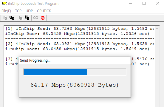
SPI 인터페이스로 이정도 속도면.. 기존에 W5300과 16비트 버스 방식으로 구현 했어야 했는데 QSPI로 간단하게 이더넷을 처리 할수 있다니..
더구나 1$ 짜리 RP2350 MCU로 이정도 이더넷 속도를 낸다면 다양한 곳에 사용할 수 있을것 같다.
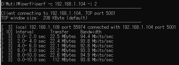
단방향으로 측정하는 iperf로 TCP Throughput을 측정해 보면 기본 설정에서 35Mbps가 측정되고 RP2350의 클럭을 150Mhz로 설정하면 40Mbps가 측정된다.

32k 메모리 설정하면 94Mbps가 측정된다. 100M 이더넷에서 거의 최대 속도를 내는것 같다.