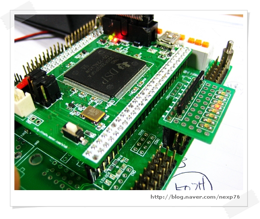
TMS320F2812 Timer제어 예제소스

|
//----------------------------------------------------------------------------- // TIMER0 #define MAIN_CLK_100MHZ 100 #define SetTimer0(TimeTickUs) ConfigCpuTimer(&CpuTimer0, MAIN_CLK_100MHZ, TimeTickUs) void cpu_timer0_isr(void);
void InitTimer0(void) { // Interrupts that are used in this example are re-mapped to // ISR functions found within this file. EALLOW; // This is needed to write to EALLOW protected registers PieVectTable.TINT0 = &cpu_timer0_isr; EDIS; // This is needed to disable write to EALLOW protected registers
// This function is found in DSP281x_InitPeripherals.c // InitPeripherals(); // Not required for this example InitCpuTimers(); // For this example, only initialize the Cpu Timers
// Enable CPU INT1 which is connected to CPU-Timer 0: IER |= M_INT1;
// Enable TINT0 in the PIE: Group 1 interrupt 7 PieCtrlRegs.PIEIER1.bit.INTx7 = 1;
// Enable global Interrupts and higher priority real-time debug events: ERTM; // Enable Global realtime interrupt DBGM }
interrupt void cpu_timer0_isr(void) { //---------------------------------------------- //Timer Interrupt Handler CpuTimer0.InterruptCount++;
//LED Toggle Led1Toggle(); Led2Toggle(); //----------------------------------------------
// Acknowledge this interrupt to receive more interrupts from group 1 PieCtrlRegs.PIEACK.all = PIEACK_GROUP1; } //-----------------------------------------------------------------------------
//----------------------------------------------------------------------------- // Main Routine //----------------------------------------------------------------------------- void main(void) { //System Initialize SystemInit();
//LED initiazle Init_Led(); Led2On(); Led1On();
//Initialize Timer InitTimer0();
//Configure CPU-Timer 0 to interrupt every second: //100MHz CPU Freq, 100ms second Period (in uSeconds) SetTimer0(100000); StartCpuTimer0();
//Enable Global interrupt INTM enable();
while(1) {
} } //----------------------------------------------------------------------------- |
 invalid-file

