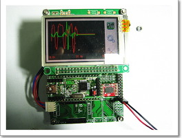
K20 EVM - Kinetis Cortex-M4 TFT LCD 테스트
Cortex-M4 코어를 가진 K20 EVM보를 이용하여 TFT-LCD 출력 테스트를 했다.
50Mhz에서 400x320 픽셀의 TFT LCD에 1프레임 출력하는데 18ms정도 소요된다.
K20 EVM TFT LCD 출력 테스트 동영상
K20 EVM - Kinetis Cortex-M4 TFT LCD 테스트
Cortex-M4 코어를 가진 K20 EVM보를 이용하여 TFT-LCD 출력 테스트를 했다.
50Mhz에서 400x320 픽셀의 TFT LCD에 1프레임 출력하는데 18ms정도 소요된다.
K20 EVM TFT LCD 출력 테스트 동영상
K20 EVM - Kinetis Cortex-M4 K20 16bit ADC 테스트
Kinetis 시리즈는 기존 Cortex-M 시리즈들에서 보기 힘든 16bit ADC를 기본으로 내장하고 있다. K20 시리즈의 경우 특히 ADC부분에 기능이 풍부해 아날로그에 있어 강점이 있는것 같다.
특히 HW 평균필터가 내장되어 있어 32 Sample까지 필터링 가능하다.
K20 ADC테스트 동영상
K20 EVM 보드를 이용하여 가변저항에 연결된 전압값을 ADC해서 그래프로 출력하는 테스트를 진행해 보았다.
K20 의 ADC 블록도
K20 ADC 레지스터
아주 복잡해 보이지만 자세히 보면 ADCx_SC1 레지스터만 설정하면 아주 간단히 ADC를 할 수 있도록 되어 있다.
5-DIFF
Differential mode enable
차동으로 받을지 싱글로 받을지 설정 한다.
0 Single-ended conversions and input channels are selected.
1 Differential conversions and input channels are selected.
4–0 ADCH
ADC 채널 선택
00000 When DIFF=0, DADP0 is selected as input; when DIFF=1, DAD0 is selected as input.
00001 When DIFF=0, DADP1 is selected as input; when DIFF=1, DAD1 is selected as input.
00010 When DIFF=0, DADP2 is selected as input; when DIFF=1, DAD2 is selected as input.
00011 When DIFF=0, DADP3 is selected as input; when DIFF=1, DAD3 is selected as input.
00100 When DIFF=0, AD4 is selected as input; when DIFF=1, it is reserved.
00101 When DIFF=0, AD5 is selected as input; when DIFF=1, it is reserved.
00110 When DIFF=0, AD6 is selected as input; when DIFF=1, it is reserved.
00111 When DIFF=0, AD7 is selected as input; when DIFF=1, it is reserved.
01000 When DIFF=0, AD8 is selected as input; when DIFF=1, it is reserved.
01001 When DIFF=0, AD9 is selected as input; when DIFF=1, it is reserved.
01010 When DIFF=0, AD10 is selected as input; when DIFF=1, it is reserved.
01011 When DIFF=0, AD11 is selected as input; when DIFF=1, it is reserved.
01100 When DIFF=0, AD12 is selected as input; when DIFF=1, it is reserved.
01101 When DIFF=0, AD13 is selected as input; when DIFF=1, it is reserved.
01110 When DIFF=0, AD14 is selected as input; when DIFF=1, it is reserved.
01111 When DIFF=0, AD15 is selected as input; when DIFF=1, it is reserved.
10000 When DIFF=0, AD16 is selected as input; when DIFF=1, it is reserved.
10001 When DIFF=0, AD17 is selected as input; when DIFF=1, it is reserved.
10010 When DIFF=0, AD18 is selected as input; when DIFF=1, it is reserved.
10011 When DIFF=0, AD19 is selected as input; when DIFF=1, it is reserved.
10100 When DIFF=0, AD20 is selected as input; when DIFF=1, it is reserved.
10101 When DIFF=0, AD21 is selected as input; when DIFF=1, it is reserved.
10110 When DIFF=0, AD22 is selected as input; when DIFF=1, it is reserved.
10111 When DIFF=0, AD23 is selected as input; when DIFF=1, it is reserved.
11000 Reserved.
11001 Reserved.
11010 When DIFF=0, Temp sensor (single-ended) is selected as input; when DIFF=1, Temp sensor
(differential) is selected as input.
11011 When DIFF=0,Bandgap (single-ended) is selected as input; when DIFF=1, Bandgap (differential)
is selected as input.
11100 Reserved.
11101 When DIFF=0, VREFSH is selected as input; when DIFF=1, -VREFSH (differential) is selected as
input. Voltage reference selected is determined by the REFSEL bits in the SC2 register.
11110 When DIFF=0, VREFSL is selected as input; when DIFF=1, it is reserved. Voltage reference
selected is determined by the REFSEL bits in the SC2 register.
11111 Module disabled.
ADCx_SC3
하드웨어 평균화 필터 설정이 가능하다.
K20 ADC 초기화 소스코드
#define ADC_CFG1_MODE_8_9_BIT 0x0
#define ADC_CFG1_MODE_12_13_BIT 0x1
#define ADC_CFG1_MODE_10_11_BIT 0x2
#define ADC_CFG1_MODE_16_BIT 0x3
#define ADC_SC3_AVGS_32_SAMPLES 0x3
void AdcInit(void)
{
SIM_SCGC6 |= SIM_SCGC6_ADC0_MASK;
ADC0_CFG1 = ADC_CFG1_MODE(ADC_CFG1_MODE_16_BIT);
ADC0_SC3 = ADC_SC3_AVGE_MASK | ADC_SC3_AVGS(ADC_SC3_AVGS_32_SAMPLES);
}
K20 ADC Read 소스코드
unsigned int AdcRead(unsigned char Channel)
{
//ADC 채널 선택
ADC0_SC1A = Channel;
//ADC 변환 완료 까지 대기
while((ADC0_SC1A & ADC_SC1_COCO_MASK) == 0)
{
}
//ADC값 출력
return ADC0_RA;
}
[K20 EVM] 보드에는 ADC8(PB0), ADC9(PB1), ADC14(PC0), ADC15(PC1) 포트에서 ADC테스트 해볼 수 있다.
PTC0 - ADC0_SE14
PTC1 - ADC0_SE15
레퍼런스 입력은 LM4040 으로 설정 가능하다.
K20 EVM - SPI 테스트 3축 가속도 센서값을 TFT LCD 그래프로 표시하기
SPI 를 쉽고 재미 있게 테스트하기 위해 가속도 센서를 활용할 수 있다. LIS3LV02 3축 가속도 센서를 SPI모드로 설정하고 확장 EVM보드에 연결하여 테스트 할 수 있다.
SPI 방식으로 센서를 설정하거나 3축 가속도 센서값을 읽을 수 있다.
K20 SPI모드 가속도 센서 테스트 동영상
K20 EVM - Kinetis Cortex-M4 SPI 테스트
Cortex-M4 K20 SPI 관련 자료 정리.
SPI클럭은 최대 25로 동작한다.
K20 SPI블록도
K20 SPI 제어 레지스터
MKL25Z 보다 기능이 많아서 레지스터가 많이 복잡해 졌다. 하지만 SPIx_MCR, SPIxCTA 레지스터만 보면 대부분의 기본 기능을 사용할 수 있다. 물론 다양한 설정으로 좀더 복잡한 기능을 구현 가능하다.
11 CLR_TXF
Clear TX FIFO
Flushes the TX FIFO. Writing a 1 to CLR_TXF clears the TX FIFO Counter. The CLR_TXF bit is always
read as zero.
0 Do not clear the TX FIFO counter.
1 Clear the TX FIFO counter.
10 CLR_RXF
Flushes the RX FIFO. Writing a 1 to CLR_RXF clears the RX Counter. The CLR_RXF bit is always read
as zero.
0 Do not clear the RX FIFO counter.
1 Clear the RX FIFO counter.
9-8 SMPL_PT
Sample Point
Controls when the DSPI master samples SIN in Modified Transfer Format. This field is valid only when
CPHA bit in CTARn[CPHA] is 0.
00 0 system clocks between SCK edge and SIN sample
01 1 system clock between SCK edge and SIN sample
10 2 system clocks between SCK edge and SIN sample
11 Reserved
K20 SPI 초기화 함수
void SPI0_Init(void)
{
SIM_SCGC5 |= SIM_SCGC5_PORTC_MASK; //Turn on clock to D module
SIM_SCGC6 |= SIM_SCGC6_SPI0_MASK;
//_SPI0_IO_INIT();
PORTC_PCR5=PORT_PCR_MUX(2);//PC5,SPI0 SCK
PORTC_PCR6=PORT_PCR_MUX(2);//PC6,SPI0 SOUT
PORTC_PCR7=PORT_PCR_MUX(2);//PC7,SPI0 SIN
//SPI_C1_CPOL_MASK
//SPI_C1_CPHA_MASK
Sbi(SPI0_MCR, SPI_MCR_HALT_MASK|SPI_MCR_MSTR_MASK);
Sbi(SPI0_MCR, SPI_MCR_DCONF(0x0));
Cbi(SPI0_MCR, SPI_MCR_MDIS_MASK);
Sbi(SPI0_MCR, SPI_MCR_CLR_TXF_MASK | SPI_MCR_CLR_RXF_MASK);
SPI0_TCR = SPI_TCR_SPI_TCNT(0x00);
Cbi(SPI0_CTAR0, SPI_CTAR_DBR_MASK);
SPI0_CTAR0 = SPI_CTAR_FMSZ(7); //8bit
SPI0_SetSpeed(SPI_SPEED_4MHZ);
//SPI Mode
//Sbi(SPI0_CTAR0, SPI_CTAR_CPHA_MASK);
//Sbi(SPI0_CTAR0, SPI_CTAR_CPOL_MASK);
//SPI0_MCR: HALT=0
Cbi(SPI0_MCR, SPI_MCR_HALT_MASK);
}
SPIxCTA 레지스터
17-16 PBR
Baud Rate Prescaler
Selects the prescaler value for the baud rate. This field is used only in Master mode. The baud rate is the
frequency of the SCK. The system clock is divided by the prescaler value before the baud rate selection
takes place. See the BR field description for details on how to compute the baud rate.
00 Baud Rate Prescaler value is 2.
01 Baud Rate Prescaler value is 3.
10 Baud Rate Prescaler value is 5.
11 Baud Rate Prescaler value is 7.
3-0 BR
Baud Rate Scaler
Selects the scaler value for the baud rate. This field is used only in Master mode. The prescaled system
clock is divided by the Baud Rate Scaler to generate the frequency of the SCK. The baud rate is
computed according to the following equation:
SCK baud rate = (fSYS/PBR) x [(1+DBR)/BR]
K20 SPI 송수신 함수
unsigned char SPI0_WriteReadByte(unsigned char Data)
{
//SPTEF - 1 이면 데이터 전송
unsigned char temp;
while (!(SPI0_SR & SPI_SR_TFFF_MASK)) ;
//Write char to SPI
SPI0_PUSHR = Data;
//SPRF - 1 이면 데이터 수신
//while (!(SPI0_SR & SPI_SR_RXCTR_MASK)) ;
while (!(SPI0_SR & SPI_SR_RFDF_MASK)) ;
temp = SPI0_POPR;
SPI0_SR = SPI_SR_TFFF_MASK | (SPI0_SR&SPI_SR_RFDF_MASK);
return temp;
}
K20 SPI SPIxTCR 레지스터
좀 특이한 사항으로 하드웨어적으로 TCR레지스터가 있어 전송 회수를 알 수 있고 이를 이용해서 버퍼 관리가 편리해 진다. 이부분은 좀더 들여다 볼 필요가 있는것 같다.
K20 SPI모드 설정
K20 EVM - Kinetis Cortex-M4 K20 UART 테스트
K20의 UART는 일반 UART 3채널로 구성되어 있다.
PTA1 -> UART0_RX
PTA2 -> UART0_TX
PTB16 ->UART0_RX
PTB17 ->UART0_TX
PTD6 -> UART0_RX
PTD7 -> UART0_TX
PTC3 ->UART1_RX
PTC4 ->UART1_TX
PTD2 ->UART2_RX
PTD3 ->UART2_TX
UART clocking
UART0 and UART1 modules operate from the core/system clock, which provides higher
performance level for these modules. All other UART modules operate from the bus
clock.
K20 UART 초기화 함수
// Serial Prot0 Utility Fuction Routine
void U0_Init(unsigned char baud)
{
//UART포트 설정
// Enable the UART_RXD function on PTA1
PORTA_PCR1 = PORT_PCR_MUX(0x2);
// Enable the UART_TXD function on PTA2
PORTA_PCR2 = PORT_PCR_MUX(0x2);
//UART0 클럭 Enable
SIM_SCGC4 |= SIM_SCGC4_UART0_MASK;
//UART disable
UART_C2_REG(UART0_BASE_PTR) &= ~(UART_C2_TE_MASK | UART_C2_RE_MASK );
//Configure the UART for 8-bit mode, no parity(디폴트 값 사용)
UART_C1_REG(UART0_BASE_PTR) = 0;
U0_SetBaud(baud);
//Enable UART
UART_C2_REG(UART0_BASE_PTR) |= (UART_C2_TE_MASK | UART_C2_RE_MASK );
}
UARTx_S1(UART Status Register 1)
DRE
Transmit Data Register Empty Flag
TDRE will set when the number of datawords in the transmit buffer (D and C3[T8])is equal to or less than
the number indicated by TWFIFO[TXWATER]. A character that is in the process of being transmitted is
not included in the count. To clear TDRE, read S1 when TDRE is set and then write to the UART data
register (D). For more efficient interrupt servicing, all data except the final value to be written to the buffer
must be written to D/C3[T8]. Then S1 can be read before writing the final data value, resulting in the
clearing of the TRDE flag. This is more efficient because the TDRE reasserts until the watermark has
been exceeded. So, attempting to clear the TDRE with every write will be ineffective until sufficient data
has been written.
0 The amount of data in the transmit buffer is greater than the value indicated by TWFIFO[TXWATER].
1 The amount of data in the transmit buffer is less than or equal to the value indicated by
TWFIFO[TXWATER] at some point in time since the flag has been cleared.
5
RDRF
Receive Data Register Full Flag
RDRF is set when the number of datawords in the receive buffer is equal to or more than the number
indicated by RWFIFO[RXWATER]. A dataword that is in the process of being received is not included in
the count. RDRF is prevented from setting while S2[LBKDE] is set. Additionally, when S2[LBKDE] is set,
the received datawords are stored in the receive buffer but over-write each other. To clear RDRF, read S1
when RDRF is set and then read D. For more efficient interrupt and DMA operation, read all data except
the final value from the buffer, using D/C3[T8]/ED. Then read S1 and the final data value, resulting in the
clearing of the RDRF flag. Even if RDRF is set, data will continue to be received until an overrun condition
occurs.
0 The number of datawords in the receive buffer is less than the number indicated by RXWATER.
1 The number of datawords in the receive buffer is equal to or greater
K20 UART 송수신 함수
unsigned char U0_GetByte(void)
{
//데이터가 수신되면
while (!(UART_S1_REG(UART0_BASE_PTR) & UART_S1_RDRF_MASK));
//데이터 읽어옴
return UART_D_REG(UART0_BASE_PTR);
}
void U0_PutByte(unsigned char Data)
{
//송신 FIFO가 비어지면
while(!(UART_S1_REG(UART0_BASE_PTR) & UART_S1_TDRE_MASK));
//데이터 전송
UART_D_REG(UART0_BASE_PTR) = Data;
}
댓글을 달아 주세요